Piezoelectric Electrical Connection and Controls
Linear Actuators
Linear actuators are fitted with 2 silver external electrodes as standard. Other materials, e.g. gold or silver/palladium are available on custom designs. The positive electrode is indicated by a black spot.
Electrical connection to the external electrodes can be achieved by mechanical contacts, soldering, with electrically conductive adhesive or wire bonding. Alternatively, linear actuators can be pre-wired for easier integration.
Mechanical contacts
Mechanical connections can be arranged by e.g. copper springs contacted to the external electrodes. It is recommended to use external electrodes of gold in order to eliminate oxidation of the electrodes. This can be done in a custom design, please contact us.
Soldering
Soldering electrical wires to the screen-printed silver electrode makes an excellent and time-stable connection but requires the appropriate equipment and experience. In order to avoid challenges with wetting the solder on the silver surface, always clean the external electrodes with a glass brush or steel wool. The solder tin must contain silver. Refer to our soldering procedure for more information.
Adhesive
Electrical connection can also be arranged by bonding wires to the external silver electrodes. We recommend a two component soft epoxy with minimum 75 % silver content and a curing temperature below 150 °C. When curing at elevated temperature, be aware that the piezoelectric actuator will generate charge (i.e. voltage) during temperature changes, so it must be connected to a resistor or shorted at all times.
Adhesive is recommended as an alternative to soldering when the actuator is operating at high frequency or subjected to thermal cycling, which may create fatigue in solder joints. We recommend using standard silver external electrodes in order to archive good electrical contact between the adhesive and electrode.
Wire bonding contacts
Electrical connection can be done by wire bonding to the external electrodes. We recommend external gold electrodes as gold generates only a thin oxide layer, which has to be penetrated in the wire bonding friction process and thereby ensures a better mechanical and electrical contact. This can be done in a custom design, please contact us.
Pre-wired actuators
As a standard, pre-wired actuators are delivered with black (negative) and red (positive) wires for single elements; white (negative) and red (positive) for stacks. We can also offer customized solutions, please contact us.
Care must be taken not to apply excessive strain on the solder joints. Apply strain relief if necessary, for example attach the wires to the structure next to the actuator.
Control
Linear actuators are controlled by applying a voltage in the specified range, for example 0 to 200V for NAC2021 between the terminals. High voltage leads to an extension of the actuator.
Learn more about our Multilayer Products
Plate Benders
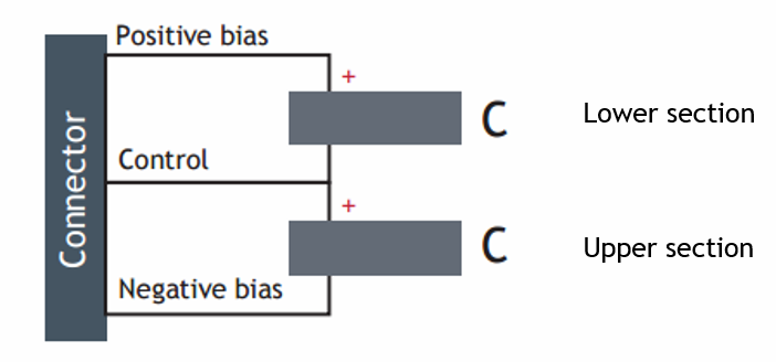
Plate benders are fitted with 3 silver external electrodes as a standard. The positive bias electrode is indicated by a black spot, the next electrode (middle electrode) is “control” and the last one is negative bias.
Electrical connection to the external electrodes can be achieved by mechanical contacts, soldering, gluing with electrically conductive glues or wire bonding. Alternatively, plate benders can be pre-wired for easier integration.
Recommendations for contacting are the same as for linear actuators.
Pre-wired actuators
As a standard, pre-wired actuators are delivered with black (negative bias), blue (control) and red (positive bias) wires. We can also offer customized solutions, please contact us.
Care must be taken not to apply excessive strain on the solder joints. Apply strain relief if necessary, for example attach the wires to the structure next to the actuator.
Control
Bending plate actuators contain two independent piezoelectric sections. The sections have a polarity, so it is important to respect a differential input voltage in the range 0-200V (for standard products) for each section.
Bending plate actuators can be controlled by:
Differential voltage control
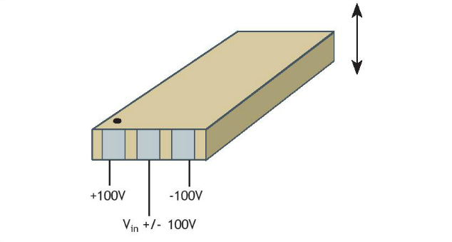
In this mode the bending can be controlled both upwards and downwards. Apply +100 V to the positive bias (indicated by the black dot), -100 V to the negative bias and a voltage Vin to the control (middle) electrode such as -100 V<Vin<100 V.
If 0 V< Vin<100 V, the plate will bend up with the black spot facing up.
If -100 V< Vin<0 V, the plate will bend down with the black spot facing up.
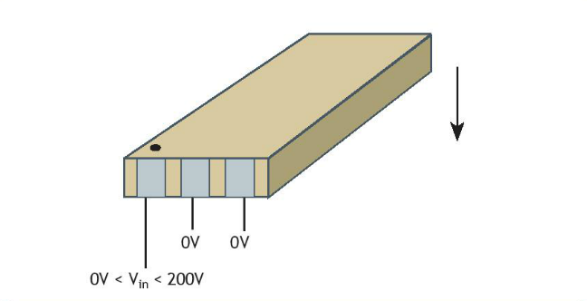
Single side voltage control
In this mode, only one active section is used and the bending can be controlled in one side only, i.e. bending down with the black dot facing up. Apply 0 V to the negative bias and control (middle) electrode, and up to 200 V to the positive bias.
Learn more about our plate benders
Ring Benders
Bending ring actuators are fitted with 3 silver external electrodes as a standard. The positive bias electrode is indicated by a black spot, the next electrode is “control” and the last one is negative bias.
Electrical connection to the external electrodes can be achieved by mechanical contacts, soldering, gluing with electrically conductive glues or wire bonding. Alternatively, plate benders can be pre-wired for easier integration.
Recommendations for contacting are the same as for linear actuators. One particularity of ring benders is that the deformation during actuation affects also the electrode area, so the electrical contacts must be designed in order not to induce stress in the ceramic and vice versa. Typically, form a small loop with the wire for strain relief.
Pre-wired actuators
As a standard, pre-wired actuators are delivered with black (negative bias), blue (control) and red (positive bias) wires. We can also offer customized solutions, please contact us.
Care must be taken not to apply excessive strain on the solder joints. Apply strain relief if necessary, for example attach the wires to the structure at a distance from the actuator.
Control
Bending ring actuators contain two independent piezoelectric sections. The sections have a polarity, so it is important to respect a differential input voltage in the range 0-200V (for standard products) for each section.
Bending ring actuators can be controlled by:
Differential voltage control
In this mode the bending can be controlled both upwards and downwards. Apply +100 V to the positive bias (indicated by the black dot), -100 V to the negative bias and a voltage Vin to the control (middle) electrode such as -100V<Vin<100 V.
If 0 V<Vin<100 V, the ring will bend down with the black spot facing up.
If -100 V<Vin<0 V, the ring will bend up with the black spot facing up.

Single side voltage control
In this mode, only one active section is used and the bending can be controlled in one side only, i.e. bending up with the black dot facing up. Apply 0 V to the negative bias and control (middle) electrode, and up to 200 V to the positive bias.

Learn more about our ring benders
2D Benders
NAC2710
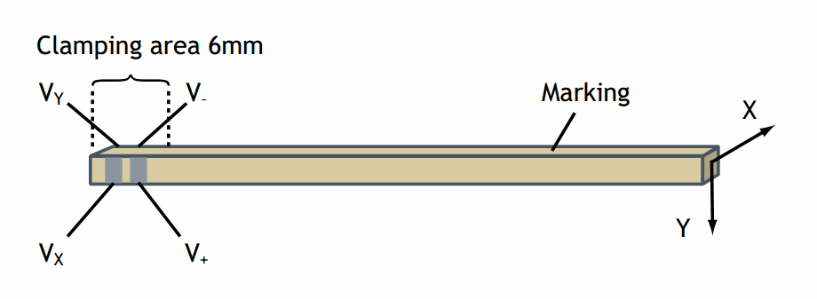
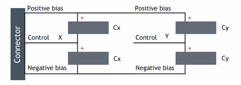
NAC2710 actuators are fitted with 4 silver external electrodes as a standard. The function of the electrodes is indicated on the sketch below. V+ is a positive bias, V- a negative bias, Vx the control electrode for X axis and Vy the control electrode for Y axis.
 Electrical connection to the external electrodes can be achieved by mechanical contacts, soldering, gluing with electrically conductive glues or wire bonding. Alternatively,
 ![]() actuators can be pre-wired for easier integration.
actuators can be pre-wired for easier integration.
Recommendations for contacting are the same as for linear actuators.
Pre-wired actuators
As a standard, pre-wired actuators are delivered with black (negative bias), blue (control for X), white (control for Y) and red (positive bias) wires. We can also offer customized solutions, please contact us.
Care must be taken not to apply excessive strain on the solder joints. Apply strain relief if necessary, for example attach the wires to the structure at a distance from the actuator.
Control
NAC2710 actuators contain four independent piezoelectric sections. The sections have a polarity, so it is important to respect a differential input voltage in the range 0-60V for each section. From an electrical point of view, NAC2710 is equivalent to two bending plate actuators sharing the same positive and negative biases.
The usual way of operating is to supply two constant voltages (bias voltages) to the following two input cables:
The two other inputs (Vx and Vy) control the position in each direction and can be driven from -30V to +30V:
- When 0<Vx<+30 V, the actuator bends in direction “X” in the positive direction.
- When -30<Vx<0 V, the actuator bends in direction “X” with the negative direction.
The same logic applies for the other voltage, Vy, which controls bending on the “Y” direction.
NAC2810
As a standard, NAC2810 actuators are fitted with 3 wires. Wire color is defined as follows: red for positive bias, yellow for control and black for negative bias.
Care must be taken not to apply excessive strain on the solder joints. Apply strain relief if necessary, for example attach the wires to the structure next to the actuator.
Control
NAC2810 actuators contain two independent piezoelectric sections. The sections have a polarity, so it is important to respect a differential input voltage in the range 0-200V for each section.
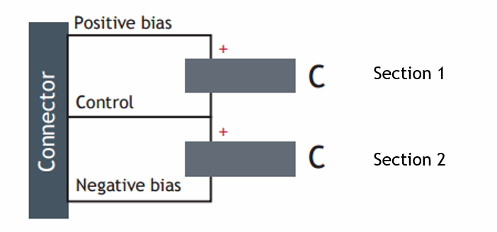
Differential voltage control
In this mode the bending can be controlled both right and left. Apply +100 V to the positive bias, -100 V to the negative bias and a voltage Vin to the control electrode such as -100 V<Vin<100 V.
If 0<Vin<100 V, the actuator will bend in the direction indicated by the black dot.
If -100<Vin<0 V, the actuator will bend in the direction opposite to the black dot.
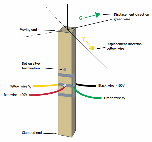
NAC2910
As a standard, NAC2910 actuators are fitted with 4 wires. The function of the wires is: red is the positive bias, black the negative bias, yellow the control wire for Y axis and green the control wire for G axis.
NAC2910 actuators contain four independent piezoelectric sections. The sections have a polarity, so it is important to respect a differential input voltage in the range 0-200V for each section. From an electrical point of view, NAC2910 is equivalent to two bending plate actuators sharing the same positive and negative biases.
The usual way of operating is to supply two constant voltages (bias voltages) to the following two input cables:
- Positive bias (red)=+100V
- Negative bias (black)=-100V
The two other inputs (Vy for yellow wire and Vg for green wire) control the position in each direction and can be driven from -100V to +100V:
- When 0<Vy<+100 V, the actuator bends along “Y” in the direction of the arrow.
- When -100<Vy<0 V, the actuator bends along “Y” with the opposite direction.
The same logic applies for the voltage on the green wire, Vg, which controls bending on the “G” direction.
Learn more about our 2D benders
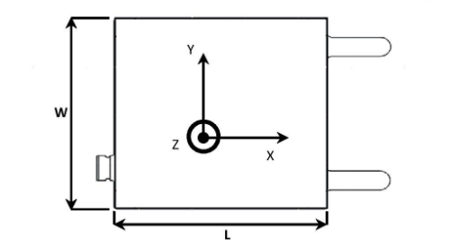
Amplified Actuators
As a standard, amplified actuators are fitted with a connector LEMO FGG.0B.304.CLAD52Z.
It mates for example with:
- EGG.0B.304.CLL (panel mount)
- PHG.0B.304.CLLD52 (cable mount)
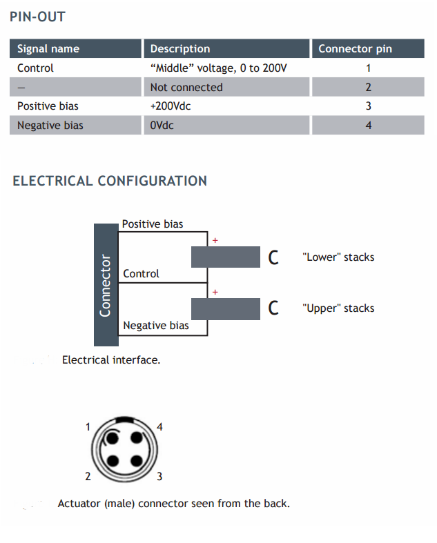
Control
Amplified actuators contain two independent piezoelectric sections. The sections have a polarity, so it is important to respect a differential input voltage in the range 0-200V (for standard products) for each section.
Differential voltage control
Amplified actuators are controlled in the same way as bending actuators.
In differential voltage control mode, the motion can be controlled both in extension and in retraction. Apply +100 V to the positive bias, -100 V to the negative bias and a voltage Vin to the control pin such as -100 V<Vin<100 V.
If 0 V< Vin<100 V, the actuator will extend (moving interface moving up).
If -100 V< Vin<0 V, the actuator will retract (moving interface moving down).
Learn more about our amplified actuators
Shear plates
Shear plate actuators are fitted with 2 external electrodes. Since shear plate actuators can be used with bipolar symmetrical electrical supply, both electrodes are identical. The direction of operation is indicated by the chamfers.
Electrical connection to the external electrodes can be achieved by mechanical contacts, soldering, with electrically conductive adhesive or wire bonding. Alternatively, shear plate actuators can be pre-wired for easier integration.
Mechanical contacts
Mechanical connections can be arranged by e.g. copper springs contacted to the external electrodes. Shear plate actuators are provided with gold plated electrodes for optimal electrical contact and to avoid oxidation of the electrodes. For demanding applications, it might be necessary to have both contacts gold plated.
It is also possible to bond a contact on the electrode using non-conductive epoxy. Provided the epoxy has been squeezed out during the curing process, this setup will provide a reliable electrical connection.
Soldering
Soldering electrical wires to the gold electrodes is not recommended since the bond is relatively fragile. It is however possible. Refer to our soldering procedure for more information.
Adhesive
Electrical connection can also be arranged by bonding wires to the external silver electrodes. We recommend a two component soft epoxy with minimum 75 % silver content and a curing temperature below 150 °C.
It is important that the adhesive doesn’t protrude on the side of the plate, as it may cause arcing and short-circuits under the high operating voltage.
Wire bonding contacts
Electrical connection can be done by wire bonding to the external gold electrodes.
Pre-wired actuators
Shear actuators are typically delivered without wires, as the preferred connection method is a mechanical contact to the gold-plated electrodes. Nevertheless, we offer pre-wired actuators fitted with white and red wires, although the function of the wires is identical due to the symmetry of the actuator.
Care must be taken not to apply excessive strain on the solder joints. Apply strain relief if necessary, for example attach the wires to the structure next to the actuator.
Control
Simply apply a voltage in the specified range (-320V to +320V) between the two electrodes. The plate will generate a strain according to the input signal. Sign convention: A positive voltage on one electrode leads to a relative displacement of this electrode towards the chamfered edge.
Learn more about our shear motion plates
Shear Stacks
As a standard, shear stacks are delivered with 2 (X stacks), 3 (X-Y stacks) or 4 wires (X-Y-Z stacks). The function of the wires is indicated by the color:
- Black: common electrode
- Red: control for X axis
- Blue: control for Y axis
- Yellow: control for Z axis
Control
The motion can be controlled independently for each axis. With the common electrode (black wire) at 0V, apply:
A positive voltage up to 320V on the red wire to generate a displacement in X direction (see sign convention below)
A negative voltage down to -320V on the red wire to generate a displacement in –X direction
Identically, the motion in Y and Z can be controlled with the voltage applied respectively on the blue and yellow wire.
Learn more about our shear motion plate stacks